
The AC cable on a solar installation carries inverter output toward the AC distribution equipment and grid connection defined by the approved design. Choosing it involves more than naming a conductor size: the cable construction, circuit arrangement, route, installation method, environmental exposure and termination details must work together.
Begin with the approved electrical design
Use the latest single-line diagram, cable schedule and inverter documentation as the basis of the enquiry. Record whether the circuit is single-phase or three-phase, the number of conductors required and the points between which the cable will run.
The responsible electrical designer should determine cable size from the design current, protective device, installation method, route length, voltage-drop limit, grouping, ambient conditions and fault requirements. Inverter capacity by itself is not a cable specification.
Specify conductor material, size and construction
State whether the approved design calls for copper or aluminium conductors, the conductor size, number of cores, conductor class and any required armouring. Include the applicable insulation and sheath construction from the project schedule rather than relying on a generic request for power cable.
If an alternative is proposed, ask the designer to review its electrical performance, dimensions, bending requirements and termination method. Conductors of different materials or construction should not be substituted solely because their nominal sizes appear similar.
Measure the route and installation conditions
Measure the actual cable route between equipment, including vertical sections, bends, entry points and the length needed for orderly termination. Separate runs where cable type, size or installation conditions change and identify the required number of parallel runs where the design uses them.
Tell the supplier whether the cable will be installed in conduit, tray, trunking, open air or another specified arrangement. Note indoor and outdoor exposure, heat, sunlight, moisture, mechanical risk and any project-specific fire-performance requirement because these conditions influence the approved cable construction.
Plan glands, lugs and cable entries together
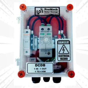
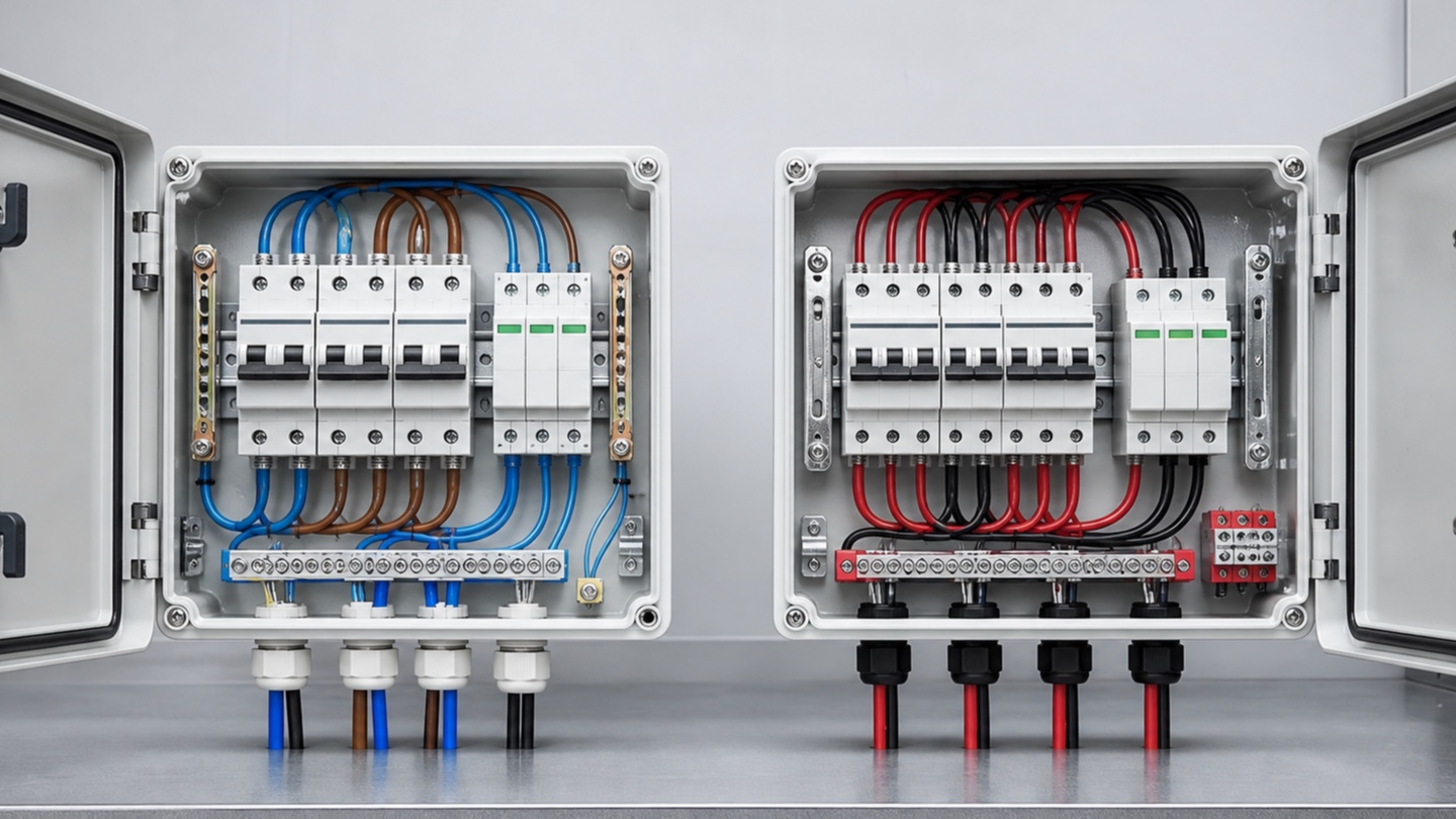
Check the inverter, ACDB and downstream equipment entries before ordering accessories. Cable outside diameter, armouring and enclosure entry size affect gland selection, while conductor material and size affect the lug or terminal arrangement.
Count termination points and specify compatible glands, lugs, shrouds, locknuts, washers, markers and earthing accessories where required. Confirm that the equipment terminals can accept the selected conductor and that there is adequate space for bending and termination.
Include identification and supporting materials
A complete cable requirement may also need route markers, phase identification, warning labels, cleats, clips, ties, tray or conduit accessories and approved sealing materials. Build these quantities from the route and support plan instead of treating them as an afterthought.
Where multiple cable drums or coils are required, ask for clearly marked lengths and plan the cuts before dispatch. A simple cutting schedule can reduce unnecessary joints, offcuts and confusion at site.
Send a quote-ready AC cable enquiry
Provide a structured requirement so the supplier can confirm the exact cable and all included accessories.
- Approved cable designation, conductor material, size and number of cores
- Required insulation, sheath, armouring and project-specific performance
- Single-phase or three-phase circuit and quantity of runs
- Measured route length, installation method and environmental exposure
- Cable outside diameter and equipment entry details
- Gland, lug, marker, support and routing-accessory quantities
- Delivery location, required date and requested test documentation
Check the supplied cable before installation
Verify the drum or coil markings, manufacturer details, cable designation, size and supplied length against the purchase order. Check that the accessories match the cable and equipment interfaces, and review any visible transit damage before the material is accepted for installation.
Cable pulling, termination, testing and energization should be carried out by qualified professionals using the approved method and manufacturer instructions. Record the installed cable identification and test results with the project documentation.
Frequently asked questions
What information is needed to order AC cable for a solar inverter?
Share the approved conductor material and size, number of cores, cable construction, circuit arrangement, measured route, installation method, environmental conditions, required length and termination-accessory details.
Can solar AC cable size be chosen from inverter capacity alone?
No. Cable sizing also depends on design current, protective device, route length, voltage drop, installation method, grouping, temperature and fault requirements. A qualified electrical designer should confirm the selection.
Which accessories should be ordered with AC cable?
Depending on the approved installation, the order may include compatible glands, lugs, shrouds, locknuts, markers, cleats, clips, ties and cable-routing accessories. Match them to the cable dimensions and equipment entries.
Key takeaway
Order solar AC cable from the approved cable schedule, not from inverter capacity alone. Specify conductor construction, route, installation conditions, measured length and every termination accessory as one coordinated requirement.