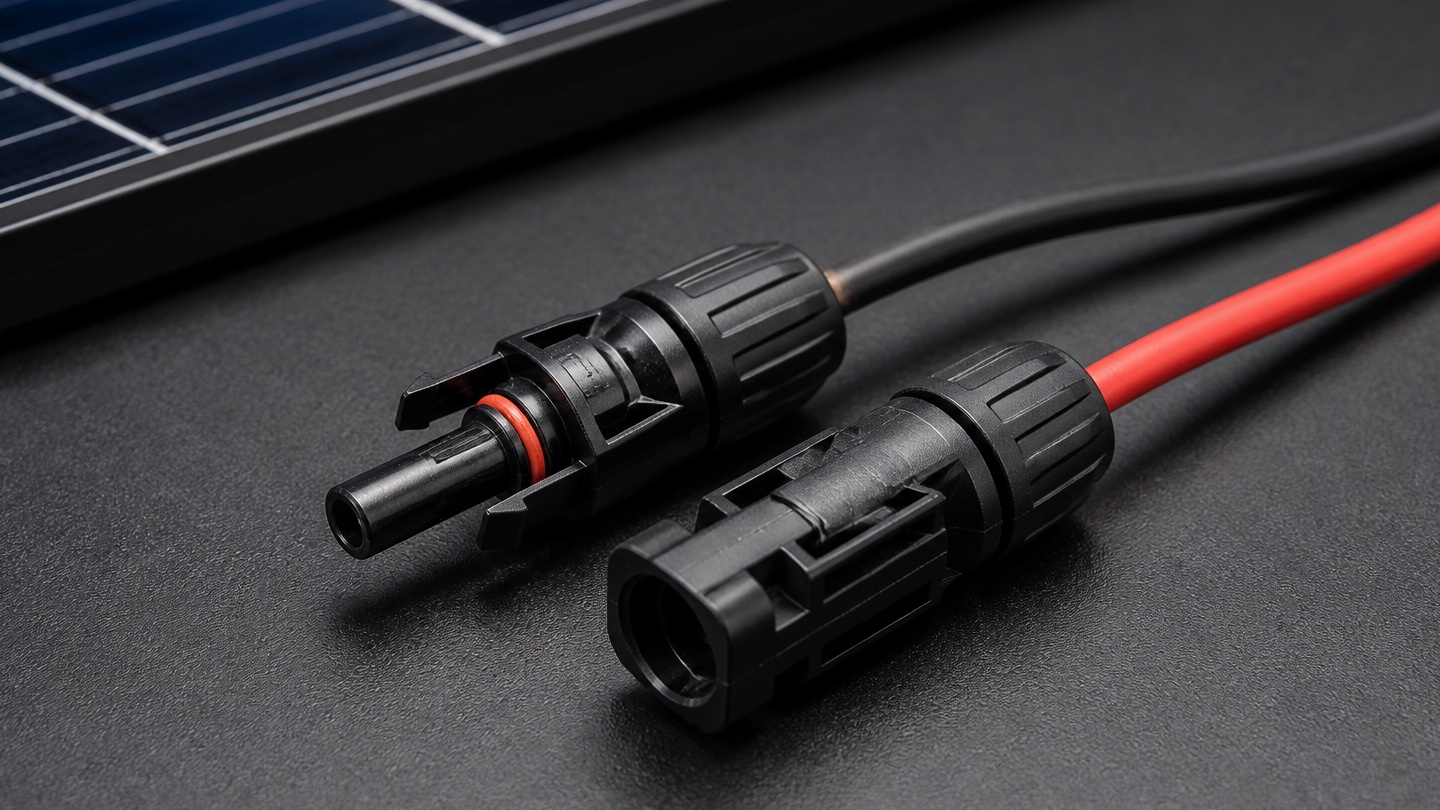

Solar earthing is a coordinated network of conductors, electrodes, bonding points and accessible connections—not a single universal kit. A complete order starts with the project’s approved earthing layout and then accounts for every termination, fixing and inspection point.
Use the earthing layout as the source of truth
Confirm the approved arrangement for module frames, mounting structures, inverter and electrical equipment, surge-protection paths and earth electrodes. The project documents should show which parts are bonded together and how the earthing network is routed.
Do not copy quantities from another project. Soil conditions, array size, equipment layout, conductor routes and the number of bonding points can all change the material requirement.
List conductors by route and purpose
Separate the conductors used for equipment bonding, structure bonding and connections to the earthing system. Record the specified conductor material, size, insulation or finish, colour identification and measured route length.
Add a controlled allowance only where the project team permits it. Measured routes and connection counts provide a more dependable basis than ordering a broad quantity of cable without a route plan.
Count every lug, clamp and termination
Each conductor end needs a compatible termination. Count lugs, clamps, washers, nuts, bolts and other connection hardware point by point, and match lug barrel size to the conductor and palm or hole size to the equipment connection.
Where different metals meet, follow the approved detail for compatible materials and corrosion control. Confirm the required crimping tools and installation method before work begins.
Confirm electrode and inspection-pit requirements
The responsible designer should specify the electrode type, dimensions, material and arrangement based on the project and site conditions. Include the approved connectors, backfill or treatment material only where specified, and identification for each electrode location.
Inspection pits should provide suitable access for checking and maintaining the connection. Confirm their size, material, cover requirement and finished location instead of treating every pit as interchangeable.
Prepare a complete earthing enquiry
Organize the purchase list by component and connection point so the supplier can check availability and compatible sizes.
- Approved earthing layout and number of electrodes
- Conductor material, size, finish and measured length
- Lug type, barrel size, palm size and hole diameter
- Bonding clamps and fasteners for each connection surface
- Electrode, connector and inspection-pit specification
- Labels, markers and corrosion-protection requirements
- Quantity, delivery location and required date
Check the order before dispatch
Review the packed material against the latest approved bill of materials. Balance conductor quantities with the required lugs and connection hardware, and verify that sizes are clearly identified.
The completed earthing installation must be inspected and tested by qualified professionals. Test requirements and acceptance values should come from the approved design and applicable project requirements.
Frequently asked questions
What is commonly included in a solar earthing kit?
Depending on the approved design, the requirement may include earthing conductors, lugs, bonding clamps, fasteners, electrodes, electrode connectors, inspection pits and identification materials. There is no universal kit for every project.
How should earthing cable quantity be calculated?
Measure each approved route and connection, then add only the practical allowance accepted by the project team. Also count the terminations required at both ends of each conductor run.
Why must lug sizes be specified separately?
A lug must match both the conductor and the equipment connection. State the conductor size, barrel type, palm dimensions and hole diameter rather than ordering by a generic name.
Key takeaway
Build a solar earthing order from the approved layout and count every route, termination and inspection point. Match conductors, lugs, clamps, electrodes and pits as one coordinated system.